Fan Gate

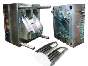
The fan gate can be considered as another variation of the edge entryway, in which the width of the fan entryway at the embellishment exceeds the breadth of the runner. One fan entryway configuration is appeared. In this plan of china high-precision mould suppliers, the width of the fan gate has been chosen to stay away from exorbitant shear rates when the liquefy streams into the depression at a high volumetric stream rate. Given the huge width of most fan entryways, the feed framework is ordinarily eliminated by a fueled gate shaper, responding saw, or switch.

One regular utilization of fan gates for the pom moulding parts manufacturers china is to give a direct liquefy stream from the entryway rather than the outspread stream that will result with the previ0us gate plans. A straightforward formed plaque application with a fan entryway is appeared. For this plan to be powerful, two rules must be met. To start with, the fan gate must traverse the width of the trim across which straight low is wanted. Second, the Ilow opposition over the width of the fan gate must be unimportant. Different fan entryway calculations have been created to modify the stream rates into the hole over the width of the fan gate. The plan is normal, and comprises of a basic space between the roundabout segment of the runner and the rectangular segment of the shape hole.

While fan entryways are viable, another option is the blaze gate or film gate. The word”flash” suggests a dissolve course through a dainty area. In like manner, the glimmer entryway comprises of a thick roundabout area that is nearby a slight rectangular segment. During embellishment, the soften will continue from the runner into the thick round area. The slim nearby area will cause the soften stream to slow, cool, and conceivably freeze while the liquefy fills the thick segment. When the dissolve hits the finish of the thick area, the liquefy weight will at that point increment essentially and power the solidified material in the meager segment to stream. Since the stream obstruction along the thick area is little contrasted with the stream opposition over the slim segment, the blaze entryway gives an almost straight dissolve stream to the depression over its width.

The idea of the blaze gate can be stretched out to a barrel shaped math to give a straight dissolve stream without sew lines. In this plan, a strong thick”diaphragm”is used to pass on the liquefy from the sprue to the internal outskirts of the form hole. A more slender entryway segment is then used to guarantee a uniform hole filling and furthermore aid the expulsion of the stomach from the embellishment. Despite the fact that the math of the stomach entryway is barrel shaped, the investigation of the shear A blaze gate can commonly be eliminated by an administrator without the requirement for power helped cutters by consistently flexing the embellishment utilizing the glimmer entryway as a pivot.

Because of the math of the stomach gate, notwithstanding, power apparatuses or a punch press are ordinarily required for de-gating. Both the blaze and the stomach entryways will leave an observer line, so it is wanted to limit the thickness of the gate; average thicknesses are on the request for 0.2 to 0.6 mm, or around 33% the thickness of the formed part. The math and slenderness of these entryways may appear to be to force over the top shear rates and weight drops upon the dissolve. In any case, these gates’ enormous widths will bring about moderately low direct dissolve speeds even at high volumetric stream rates. Thus, these gates can be viably intended to give moderate shear rates and weight drops.
Feed System & Runner

The plan of the feed system is basic to infusion shaping yet is regularly dubious. One basic issue is the ability of an accessible trim machine to fill the shape with a material whose stream attributes are obscure. Then again, there might be vulnerability with regards to the specific liquefy stream rates and weights that are needed to appropriately adjust a family mold or complex multi-gated part / injection molded part.

In questionable circumstances, the form architect ought to determine feed system measurements that are”steel safe,”which implies that the plan should require the expulsion of less shape steel than may eventually be required. Accordingly, the shape architect may wish to adjust the feed system measurements down a couple of standard sizes. Thusly, the shape originator will force a more prominent weight drop and utilize less material than anticipated by the investigation. There is a sensible possibility that the modest feed system may work appropriately. Besides, on the off chance that the feed system requires at least one changes, at that point the”steel safe” plan might be effectively machined with bigger runner sizes to improve the form execution.

Mold manufacturing factory suggests a”steel safe” runner plan if the examination showed an ideal distance across of 4.6 mm for a chilly runner. On the off chance that the feed system examination brought about a runner distance across of 4.6 mm, at that point the shape creator may indicate a measurement of 4.5 mm or even 4 mm for a “steel safe” plan. By correlation, if the form fashioner had gathered together to 5 mm, the plan would have given a lower pressure drop yet expended pointless material all through the shape’s whole lifetime. Moreover, in the event that the disintegrate wanted to lessen the 5 mm breadth, at that point the form would require more broad adjust including pocket processing of the old feed system, the assembling and fitting of a properly measured supplement, welding or potentially the expansion of latches, lastly the arrangement of the new, littler feed system. While this model zeroed in on steel safe plan of cold runners, the steel safe idea is additionally relevant to hot runner plans.

As recently portrayed by oem/odm injection mold factory, the most widely recognized sorts of feed systems are cold runners and hot runners. The two kinds of feed systems have detriments. With cold runners, there is impressive material waste related with the arrangement of the feed system just as the potential for broadened process durations. With hot runners, there is the extra expense and intricacy related with the temperature control systems, just as the potential for temperature varieties and shading change issues.

As an option for high precision mould china in contrast to both cold runner and hot runner designs for injection molding china, the protected runner was planned trying to kill these impediments. The plan design is fundamentally the same as a three-plate shape with a runner segment 15, a cavity segment 16, and center areas 17. The runner format is likewise comparable with a sprue 19 passing on the liquefy through the plate thickness to essential and optional runners 18 that pass on the soften over the splitting plane to a second arrangement of sprues, 22 and 23, which pass on the dissolve down to the shape depressions. Contrasted with a customary three-plate shape, be that as it may, all fragments of the feed system are intentionally intended to have huge distances across. In expansion, the runner segment 15 is made sure about to the depression area 16 and doesn’t open at all during ordinary embellishment.

During the trim cycle, the soften is infused from the spout of the embellishment machine and totally flls the feed system. A skin, 18a and 18b, promptly shapes on the outside of the runners. Be that as it may, the set skin doesn’t completely engender all through the runner, since the warm conductivity of plastic is exceptionally low and each forming cycle passes on warmed polymer dissolve from the trim machine all through the feed system.

Accordingly, the measurement of the liquid center remains almost predictable during the trim cycle. Thusly, the protected runner can be worked as a hot runner, though with no warmers, thermocouples, or temperature regulators. The shading change issue is settled by eliminating the completely hardened feed system with the arrival of runner area 15 from the cavity segment 16. This article is from http://www.automoldchina.com/

Stack Mold

At the point when the plastic liquefy is injected into the mold hole at high weight by china injection mould maker, huge clip power is needed to keep the mold shut so the dissolve doesn’t get away from the mold cavity. Since the cinch power is relative to the extended territory of the mold cavities, the brace power increments relatively with the number of shape cavities over the splitting plane. In any case, on the off chance that the pits are”stacked” one on head of another, at that point the clip power used to close one lot of cavities can likewise be utilized to close any arrangements of pits that are in the stack.

One such stack mold configuration from china precision molds manufacturers, which was intended to shape two vinyl records with the clasp power and process duration typically used to mold one vinyl record. In this plan, two arrangements of stampers are mounted between an internal plate, 12, and two external plates, 14 and 16; the inward plate, 12, is guided by course, 20. The dissolve streams from the spout, 54, of the embellishment machine through broadened sprue, 40, to two arrangements of holes where the records are framed. After the plastic sets, the dissolve shut-off pole, 65, is incited to seal the sprue bay, 51, with the shut-off, 66. This activity additionally associates the sprue, 40, to the chute, 64, to such an extent that the sprue might be taken from the moldings with initation of the sprue take out bar, 75. The shaped records are then catapulted subsequent to withdrawing the sprue take out pole and opening the mold.

There are two in-sufficiency in the mold plan. To begin with, the stack shape requires the arrangement of a sprue, which is scrap. Second, the soften stream to the two holes isn’t adjusted, because of the extra length of the sprue to one side pit. Both these defliciencies are settled in present day stack mold plans that use hot sprinter frameworks.

In this plan of plastic injection molding services china, a focal moving plate, 56, houses two arrangements of depressions, 60, on contradicting separating planes, 62 and 64. A hot complex, 65, conveys the polymer soften to the pits through the sprinter, 70, and ensuing drops. The plan utilizes tw0 single hub valve entryways to convey the liquefy from the trim machine spout, 17, over the splitting plane, 62, and to the complex, 65. During filling and pressing phases of the trim cycle, the actuators, 50 and 54, withdraw the valve pins, 24, to convey the liquefy from the n0zzle to the complex. Something else, the valve pins seal the feed framework during the plastication, Cooling, and mold reset stages.

While the stack shape configuration expands the stack stature and intricacy of the mold, it empowers the embellishment of two arrangements of pits with a similar process duration and clasp power as a solitary arrangement of cavities. Besides, the stream to the two arrangements of holes is totally ba speared and there is no material waste related with the hot sprinter feed framework. Given the huge part cost decreases managed by this sort of stack mold configuration, stack molds are now very normal with two, three, and four degrees of depressions. Unmistakably, the stack shape configuration requires the cautious adjusting of potential preparing cost reserve funds with issues identified with speculation, upkeep, shading change, stack stature, and injection volume by oem injection mold factory.

This article is from http://www.automoldchina.com/.

Runner

For injection moulder services, form originators ought to consider the utilization of cold runner shut-offs to furnish disintegrates with assembling flexibility. A portion of the regular employments of runner shut-offs include:

to incidentally close off the stream to harmed holes until form fix can be performed, to choose distinctive com binations of shape cavities to run in a family shape compliant with creation prerequisites, and to modify the gating and stream in a multigated part.

In that capacity, runner shut-offs can be utilized in precision plastic injection mold factory by the disintegrate to abstain from embellishment damaged or undesired parts just as improve the nature of multigated parts without retooling. The utilization of runner shut offs to incidentally seal harmed cavities is fairly questionable since it 1) expects changes to the embellishment machine measure conditions (particularly shot size and infusion speed), and 2) can unbalance or in any case adjust the stream and warmth move between pits. Except if the disintegrate re-qualifies the trim cycle for the new depression design, hole shut-offs ought not be utilized in business creation for high accuracy forming applications.

An isometric, detonated get together perspective on a runner shut-off plan is appeared. In this plan of oem/odm industrial mould factory, a pivoting round and hollow supplement, thing 50, is held between an external packaging, 40, and a retainer, 60, that adjoins the back plane of a barrel shaped pocket cut into the form plate. The runner supplement might be promptly turned with the form introduced in the embellishment machine. A spring-stacked ball is utilized to connect with grooves, 54, on the rear of the addition to guarantee that the supplement doesn’t accidentally turn during ensuing embellishment cycles. While the plan gives a runner a”T”branch, the shut-off get together comes incomplete and can be given different runner setups, the most well-known being”T,””L,”and straight. Economically accessible shut-offs are accessible for around $1 50 for use with runner measurements going from 2 mm to 9.5 mm. When planning the feed system for cold runner forms, the shape planner ought to determine runner widths that are machined with promptly accessible cutting apparatuses.

The most usually accessible sizes for tightened, square, and ball end plants are 1/32″,1/16″, 3/32″,1/8″, 3/16″, 1/4″,5/16″, 3/8″, 7/16″,1/2″, 2 mm, 3 mm, 4 mm, 4.5 mm, 5 mm, 6 mm, 8 mm, 10 mm, and 12 mm. To accomplish the most effortlessly delivered cold runner plan, it might be important to adjust the measurements to standard sizes and check the exhibition of the plan with investigation. Nonetheless, if nonstandard runner sizes accommodate less material use and more adjusted dissolve stream, at that point nonstandard runner widths can and ought to be indicated.


Hot runner systems are correspondingly accessible with a scope of standard bore sizes, commonly stepped in 1 or 2 mm increases. The standard distances across and plans will fluctuate by hot runner provider. A few providers may give bore distances across of 5, 7, and 9 mm while different providers may give widths of 4, 6, 8, and 10 mm.

Most serious providers of china high precision mold supplier will perform stream examination of the feed system and give suggestions with respect to the hot runner innovation and measuring. Notwithstanding, the form fashioner ought to confirm the suitability of the proposals. Likewise with the detail of custom widths for a cool runner, numerous hot runner providers will give custom measuring at an additional expense. This article is from http://www.automoldchina.com/.

Feed System Pressure

When the layout and lengths of the feed system have been resolved, the widths of each bit of the feed system ought to be resolved by china precision molds factory.

The progression of polymer soften through the feed system is in the laminar stream system. For china precision molds manufacturers to confirm laminar stream, the Reynolds number, Re, ought to be under 2300. Where is the volumetric stream rate (regularly on the request for 50,10 6 m3/s), .

Pmelt is the thickness (regularly on the request for 1000 kg/m}), met is the clear consistency (commonly on the request for 100 to 1000 Pa-s), and D is the sprinter measurement (ordinarily on the request for 0.01 m). Subbing average qualities for the factors in Eq.6.2 demonstrates that the Reynold’s number is on the request for 0.1. In that capacity, the stream system is a long way from violent, inertial impacts are immaterial, and the weight drop, AP, can be assessed utilizing the well-known Hagen Poiseuille condition. Where L and R are the length and span of a segment of the sprinter. To give a precise gauge of the weight drop utilizing the Newtonian model, the clear consistency ought to be assessed for the polymer soften at a proper shear rate.

For a force law liquid, the weight drop can be assessed straightforwardly without figuring of the shear rate.

In the model of oem/odm injection mold factory, The investigation accept that ABS is formed with a volumetric stream rate at the gulf of 125 cc/s. To abstain from figuring the shear rate in each part of the sprinter, the force law model is utilized with k equivalent to 17 ,000 Pas/and n equivalent to 0.35.

The drag of the hot sprue bushing is 90 mm long and has a range of 6 mm. The volumetric stream rate through the hot sprue bushing is 125 cc/s, so the weight drop through the sprue.

After the hot sprue bushing, the liquefy branches into two stream streams. Since the multigated PC bezel is almost symmetric, the stream rate through every leg of the hot sprinter system is thought to be half of the delta stream rate, or 62.5 cc/s. Every leg of the complex is 1 18 mm long with a sweep of 5 mm, so the weight drop through the complex.

To ascertain the weight drop through the spout, the most exact gauge might be given by examining each fragment of the tightened bore. Given this specific spout bore math, be that as it may, a sensible gauge might be gotten by demonstrating the tightened bore as a consistent segment with a sweep of 3.5 mm and a length of 108 mm. The weight drop is then Once the weight drop through the feed system is investigated, it is conceivable to modify the feed system configuration to improve the presentation. Different emphases of plan and investigation might be led to get a plan that gives a low weight drop while expending almost no material. Multivariate enhancement is a mathematical method that could be utilized to at the same time limit the weight drop while limiting the sprinter volume. Nonetheless, this methodology expects time to actualize and approve while smothering the subtleties of the examination from the fashioner.

This article is from http://www.automoldchina.com/.

Feed System Types

While  china molds design services are handling the two-plate mold, three-plate mold, and hot sprinter mold plans contrast fundamentally in structure and capacity, the plan of the feed systems ought to cling to essential rules as recently examined. To sum up, the feed system should:

  1. Force a negligible weight drop, ordinarily no more prominent than half of the compel needed to fill the mold pits or 50 MPa;
  2. Expend a base measure of material, ordinarily no more prominent than 30% of the volume of the mold holes for cold sprinter molds or 1 00% of the volume of the mold depressions for hot sprinter molds; and
  3. Not broaden the mold cooling time.

Truly, many feed systems have been planned with the expectation to keep up a similar direct speed as the soften courses through the sprue, essential sprinter, and so on. The liquefy velcity can be safeguarded in a spread rlnner system by setting the breadth of the downstream distances across.

While this plan rule of china injection mould maker is straightforward and appears to be instinctive, the subsequent plans are second rate as for the forced weight drops and the devoured plastic material. All things considered, a building procedure for feed system configuration is next introduced dependent on the investigation of the previously mentioned three destinations.

The kind of feed system is frequently indicated as a component of the mold quote by the mold fashioner since it is either evident or determined by the client. Nonetheless, on the off chance that the kind of feed system is unsure, at that point the mold creator ought to think about the necessities of the embellishment application and the abilities of the decay. Table 6.2 gives a correlation of the properties for normal feed system types.

Some conversation is justified with respect to Table 6.2. To start with, the forthright venture alludes not exclusively to the expense of the mold plan and related parts, yet additionally to the time needed to produce and test the completed mold. For example, a two-plate mold with two holes may cost $20,000 and require half a month to finish.

By correlation, a 64cavity stack mold may cost $1 ,000,000 and require a while to finish. For some quickened item improvement extends, the additional time might be as huge an issue as the additional expense. Gracefully chain co-ordinations can likewise be an issue. For instance, a client may like to develop twelve moderately basic mold, each having four holes. A couple of molds would then be able to be independently worked in Europe, china automotives injection mold manufacturers of Asia, and America. While the process duration and productivity isn’t as high as a solitary hot sprinter mold with high cavitation, this methodology may decrease the underlying mold improvement time, give repetition to mold disappointment, and take into consideration diminished thoughtfulness time in the gracefully anchor in light of changes in buyer request.

The ability of the disintegrate is likewise an issue concerning the choice of the kind of feed system by china high precision injection molding machine. While all decays are relied upon to work two plate mold, some disintegrates may not be acquainted with the correct arrangement, activity, and support of three plate molds, protected sprinter molds, or hot sprinter molds. The activity of stack molds, while not essentially more intricate than that of a traditional hot sprinter, may appear to be overwhelming to some disintegrates and require helper regulators that are not accessible. Therefore, the mold originator ought to check the capacities of the decay if the sort of feed system has not been determined.

The material and cycle productivity might be the essential driver to utilize more refined feed systems. Since the financial aspects are reliant upon the particulars of the embellishment applications, cost assessment ought to be per-molded for each feed system type to decide the most suitable plan. It might be helpful to play out an affect ability examination to recognize the danger of under-or over-planning the mold for a focused on creation volume.

This article is from http://www.automoldchina.com/

Filling Patterns

Filling patterns can be promptly anticipated utilizing the lay level examination strategy and are valuable to comprehend the conduct of the liquefy in filling the shape, finding doors, recognizing sew line areas, and aiding different parts of mold plan by pom moulding parts manufacturers china. Examination will be performed for a five-sided compartment with a width, length, and tallness of 100 mm, 160 mm, and 60 mm, separately.

Accepting that a two-plate form will be utilized by the mould manufacturers factory, the holder will be gated at the edge of a side divider, To foresee the filling designs, the sides of the compartment are”cut” at the corners and the side dividers collapsed down to make a lay level. The door area is next recognized. The stream will radiate from the entryway, creating a round liquefy front. In that capacity, a curve might be drawn from the entryway speaking to the situation of the soften at a given point in time.

Each bend relates to the area of the liquefy front at an alternate time step; the separation between the curves is equivalent to the straight dissolve speed times the time step. While the liquefy area at the first run through advance is right, the soften will hit the contiguous side divider before the second’s over time step. All things considered, it is important to draw extra curves on these contiguous side dividers mirroring the situation of the soften stream at different time steps. To effectively foresee the stream conduct, the investigation must keep up a similar stream obstruction between the liquefy streaming in the different segments of the form. This can be practiced by making a “phantom”gate and keeping up a similar stream lengths from this “apparition” entryway as from the genuine door.

For each time step, which has been considered by injection molding service china, the length of stream is expanded and a curve of comparing sweep is drawn. Meeting bends comparing to a similar time step are then tended to. The stream is progressed with more ghost doors included varying until the stream all through the whole lay level is made.

High-precision molds made in china shows this liquefy front forecast measure and the subsequent soften front areas for the holder. It is seen that the stream races around the side dividers and will shape a weld line and a gas trap as an afterthought divider inverse the entryway.

This wonder, known as”race – following,” is very regular in shaped parts and can happen when the length of stream around the border of the embellishment is not exactly the length of stream over the center line of the part.

For this situation, race-following happened in light of the fact that the 60 mm profundity of the holder is more than one a large portion of the 100 mm width of the compartment. While the weld line isn’t alluring, a gas trap on a side divider, for example, appeared in china high-precision mould suppliers is particularly risky since it is hard to vent. In that capacity, the caught air will probably combust, causing a consume imprint to show up at this area.

This article is from http://www.automoldchina.com/

Mold in Natural Law

Newton’s law of consistency expresses that the shear pressure, T, between equal layers of stream is corresponding to the shear rate. where the coefficient μ is the clear thickness and is expected consistent for “Newtonian” liquids.

Plastic injection molding services china analyzes the Newtonian model against the non-Newtonian conduct gave by the Cross-WLF model for a medium consistency PC at 280°C. As recently expressed, the polymer soften is known to be non-Newtonian. Consequently, the Newtonian model gives a careful gauge to the consistency just at a shear pace of 7000 1/s. The Newtonian model overestimates the thickness at higher shear rates and thinks little of the consistency at lower shear rates. All things being equal, the Newtonian model is the most straightforward and can give sensible designing appraisals when a delegate shear rate is utilized. Note that china high precision injection molding machine utilizing the Cross model’s Zero shear thickness, 97o, as the clear consistency would bring about a critical overestimation of trim shear stresses and weights since it disregards the shear diminishing conduct close to the pit dividers where most of the stream conductance is produced.

Newton’s law of consistency expected that the thickness isn’t a component of shear rate. At the point when a material doesn’t comply with this law, it is supposed to be non-Newtonian. One of the easiest and most regular non Newtonian models is the force law model, which expresses that the consistency is an exponential capacity of the shear rate. shere k is a consistency list illustrative of the estimation of thickness assessed at a shear pace of one complementary second and n is the force law record.

Figure 5.7 analyzes the force law model against the non Newtonian conduct gave by the Cross-WLF model for a medium consistency PC at 280°C. It is seen that the force law model gives superb evaluations of the consistency at higher shear rates however overestimates the thickness at lower shear rates. Therefore, it ought normal that the force law model will give more precise evaluations than the Newtonian model yet overestimate the weight drop contrasted with the Cross-WLF model, since it over-predicts the consistency at lower shear rates.

It ought to be noticed that a few gums, for example, a few evaluations of polypropylene, progress to a force law system at low shear rates. For these kinds of materials, there is no obvious New tonian level and the force law model can be required to give awesome assessments. For different materials showing a huge Newtonian level, for example, the polycarbonate just examined, the force law model can intentionally fit to a littler shear rate system important to give more exact outcomes.

For stream of a force law liquid, the speed profile through the thickness is an element of the force law file, n. The volumetric stream rate is the basic of the speed over the thickness times the width, W. It ought to be noticed by chinese mold component machining manufacturers that a force law list equivalent to one returns the force law model to the Newtonian model. As the force law list diminishes, the consistency displays expanded shear diminishing with the end goal that the polymer liquefy streams quicker close to the side divider. As the force law record approaches zero, a fitting stream creates in which the liquefy speed is practically consistent through the thickness. These practices are graphically portrayed during china mould make services. Note that that the liquefy speed at the inside line diminishes to keep up a consistent volumetric stream rate as the force law file diminishes.

With the force law model, the shear rate at the divider isn’t needed to assess the weight drop, however it might be valuable to ascertain to dodge over the top shear rates or check the thickness of the liquefy. It tends to be determined from either the normal straight stream velcity or the volumetric stream rate.

This article is from http://www.automoldchina.com

the Cavity and Parts Moulding

China precision injection plastic parts factory knows that shut-offs are contact regions between the center addition and the hole embed that different segments of the pit framed between the center and hole embeds. A shut-off should be characterized for every window or opening in the formed part. On the other hand, on the off chance that a section has no windows, similar to the cup, at that point no shut-offs are characterized. The edge of each shut-off is likewise characterized by a splitting line, which ought to be situated in a non-visual territory where an observer line or slight lashing would not lessen the estimation of the shaped part.

For instance, the PC bezel has one enormous opening over the splitting plane for the showcase. A shut-off is essential over the whole region of the opening, there are basically two potential areas for the shut-off’s splitting line, relating to the top and base of the rack that underpins the presentation.

Either area (or even any area in the middle of) would almost certainly be satisfactory with oem/odm automotives mould factory since the whole rack is escaped see.

With the meaning of the splitting plane and all fundamental shut offs, the center addition and the hole embed have been totally isolated. To make the pit and center embeds, the length, width, and stature of the additions must be characterized.

Depression and center supplement measuring rules are portrayed that have been grown so the length and width of the hole and center additions are sufficiently huge to:

(1) encase the pit where the part is framed,

(2) withstand the powers coming about because of the liquefy pressure applied upon the region of the pit,

(3) contain the cooling lines for eliminating heat from the hot polymer dissolve, and

(4) contain different parts, for example, holding screws, ejector pins, and others.

These prerequisites recommend making the center and depression embeds as extensive as could be expected under the circumstances. For littler shaped parts, expanding the measuring the center and pit supplements may have little included expense. Nonetheless, the expense of bigger center and pit additions can get unnecessary with increments in the quantity of cavities or shaped part size.

The stature measurement is regularly dictated by two necessities. To start with, the center and depression addition ought to have enough tallness above and underneath the shaped part to securely pass a cooling line. Cooling line distances across commonly extend from 4.76 mm (3/16″) for littler molds to 15.88 mm (5/8″) for enormous molds. For the most part, enormous supplements with bigger cooling lines will give quicker and more uniform cooling. While cooling line configuration will be later talked about, the base tallness measurement between the shaped part and the top or base surface of the supplement is normally multiple times the distance across of the cooling line to stay away from over the top pressure. The underlying stature measurements for the center and cavity embeds are appeared.

Second, the center and cavity supplement ought to have a tallness that is coordinated with the stature of accessible cavity and center addition retainer plates (the”A”and”B”plates). These plates are usually accessible in %” increases for shape bases planned in English units, and in 10 mm increases in metric units. Accordingly, the supplement statures ought to be chosen up in size to such an extent that the essences of the hole and center additions are flush or marginally raised concerning the”A” and”B”plates on the splitting plane.

It ought to be noticed that the tallness of the center addition as shown isn’t its complete stature but instead the stature measurement from the back surface to the splitting plane. For materials acquisition and cost assessment, the all out tallness of the center addition ought to likewise incorporate the stature of the center over the splitting plane in addition to some wellbeing stock to take into account machining and wrapping up.

This article is from http://www.automoldchina.com/.

Mold Base Size

It’s a common information for China high precision mold manufacturers that to get the right mold base for the production should take different conflicts into consideration. Sometimes the result may come out disappointed if we miss some small parts, which may lead to rework all moulding parts. The size of the mold base is resolved essentially by the region needed to oblige all the hole embeds per the planned depression format for china precision plastic injection mold factory. An essential issue for china precision injection plastic parts factory, nonetheless, is the potential for strife between the situations of the cavities and other mold parts, (for example, pioneer pins, manage bushings, and others). Besides, there is the potential for strife between cavity emotionally supportive networks, (for example, cooling lines, ejector pins, uphold pillars, and so forth.) and other mold parts, (for example, pioneer pins, direct bushings, and others). Due to these conflicts, mold bases are frequently estimated bigger than what might initially be thought of.

The concealed region in Fig. 4.21 speaks to the usable zone of the splitting plane into which the center and hole additions can be put. Ejector return pins are situated to one side and right of this region, while control pins and attachment head top screws are situated over this region. A dimensional recompense equivalent to in any event one-portion of every part’s distances across is given between the mold cavity and the encompassing segments to keep away from exorbitant worry during the mold’s activity.

Given the cavity design and its mathematical envelope, a mold base with an achievable length and width is chosen. Standard mold bases from oem/odm automotives mould factory are broadly accessible from 200 mm up to 1000 mm on a side. While determining a mold base, it is additionally important to indicate the tallness of the”A”plate, the stature of the”B”plate, the tallness of the help plate,”S,” and the separation of the ejector travel,”E”. The absolute stack stature is characterized as the good ways from the base of the back clip plate to the head of the top clasp plate.

Regarding mold base choice, the tallness of the”A”and”B”plates are separately coordinated to the stature of the hole and center embeds as recently examined. The stature of the help plate, “S,” is typically decided from the mold base provider dependent on the tallness of the”A”and”B”plates, however the tallness of the help plate can be unique arranged to shifting measurements. The movement of the ejector plate ought to be chosen to discharge the part from the mold. Frequently, the ejector go is set to be equivalent to the profundity of the molded part. From the ejector travel, the tallness of the ejector lodging, dimension”C, is allocated by the mold base provider.

China automatives injection overmould manufacturers know it clearly that while choosing a mold base, it is additionally important to indicate an opening breadth for the sprue. This measurement is of lesser significance since the sprue bushing might be supplanted or machined, or the embellishment machine nozzle changed, to coordinate the sprue to the nozzle as later examined.

This article is from http://www.automoldchina.com/.