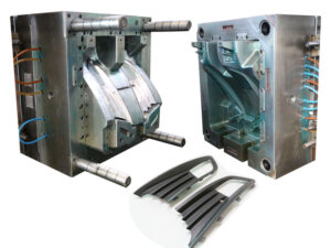
Shrinkage

The volumetric shrinkage compares to shrinkage in each of the three spatial components of the shaped part. On the off chance that a material displays similar properties toward each path, it is supposed to be “isotropic.” Most unfilled plastics show isotropic conduct, with the end goal that the properties of the shaped part are comparative in bearings corresponding to the heading of stream, opposite to the course of stream, and over the thickness.

On the off chance that a material is isotropic, at that point it should show a similar straight shrinkages in china mould-building services, every which way. Consider a unit block and a contracted 3D shape as appeared in high precision plastic making mould china, in which the contracted block has a general change in the volumetric shrinkage of Fv Each side of the contracted 3D square has been decreased from L to L(1-s), where s is the direct shrinkage.

The volume of the unit shape is L3. The volume of the contracted solid shape is L3. ry, which to keep up protection of mass should likewise approach (L(1-S))3 subsequent to contracting. This prompts the condition. Register the straight shrinkage for the bezel formed in ABS. Expecting the past conditions, the general change in the volumetric shrinkage was 0.99 1%,This prompts the isotropic shrinkage of.

This shrinkage gauge is underneath the suggested shrinkage pace of 0.6% gave by the material provider. The distinction, which isn’t really a mistake, is likely because of the generally high pressing weight of 66 Mpa (9600 psi) that was expected for this slight divider application.

A few materials, for example, fluid gem polymers and glass filled polymers, show material properties that are a subject to the stream bearing. For these anisotropic materials, the particles or potentially filaments can turn out to be profoundly adjusted in the stream field during the filling and pressing stages as appeared in Fig. 10.6. As appeared by the viewpoint proportion and heading of the ovals, the direction through the thickness can be very intricate. The shear stream during the flling and pressing stages will in general arrange the plastic soften toward move through a considerable bit of the thickness.

Since glass has a lower coefficient of warm development, the material will likewise will in general have lower shrinkage in the stream bearing than in different ways. The connection among volumetric and anisotropic straight shrinkage is appeared in high precision plastic injection mould suppliers, where the variable a speaks to the part of anisotropy in the stream bearing identified with the other two headings.

Accept that an ABS is utilized by mould manufacturing factory to shape the bezel with 15 % glass fiber by weight. (Such a material exists for this application, known as Cycolac CRT3370.} Estimate the anisotropic shrinkage if the plastic material is referred to shrivel half as much in the stream bearing contrasted with different headings.
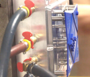
To begin with, the expansion of 15 % glass fiber will decrease the volumetric shrinkage since the glass has very lttle warm extension contrasted with the plastic. Since glass has a thickness of 2600 kg/m; and the unfilled or”neat” ABS has a thickness of 1040 kg/m3, the volume of the glass fiber in the ABS. The arrangement has united after two cycles. The shrinkage, s, approaches 0.35 % in the cross stream and thickness headings, and the shrinkage in the stream course, is 0.18%.

This article is from http://www.automoldchina.com

Processing Conditons

The essential objective of shrinkage investigation for plastic injection moulding china is to comprehend the shrinkage conduct of the plastic and its reliance upon the handling conditions. By understanding the shrinkage conduct, recomnmendations can be made with respect to the shrinkage rates to be utilized for shape configuration just as direction to the decay in regards to the determination of preparing conditions to convey the predefined resiliences.

To get high-precision molds made in china, the initial phase in foreseeing the shrinkage is to appraise the weight and temperature of the polymer liquefy from the mold calculation and expected machine set focuses. Since the specific preparing conditions are not known previously, the shape architect may accept that the soften temperature is equivalent to the mid reach temperature suggested from the material provider. The soften pressure is more hard to anticipate since the disintegrate will change the filling speed and pressing strain to address an assortment of necessities (counting shrinkage). Nonetheless, a typical embellishment practice is that the pressing weight is at first set to 80% of the compel needed to fill the shape.

For the Tablet PC Bezel shaped of ABS (Cycolac MG47), the liquefy temperature is thought to be 239°C. The flling pressure was recently examined in Section 5.5.2 and discovered to be 90 MPa for two entryways taking care of into the pit with a 1.5 mm ostensible divider thickness. As needs be, the liquefy pressure during pressing is thought to be 72 MPa. The shape temperature is additionally thought to be at the center of the ecommended range for the coolant temperature, which rises to 60°C.

The compressibility (or PvT) conduct of the polymer liquefy can be demonstrated by the twofold space Tait condition [5], which determines the particular volume, v, as an element of the dissolve’s weight and temperature [6]. The term”double domain”implies that the particular volume is demonstrated independently in the strong and dissolve states. The progress temperature between the strong and dissolve states is demonstrated as a component of weight, where bs is the progress temperature at zero weight, and b。is the pace of progress of the change temperature as for pressure. For temperatures beneath the change temperature, the reference explicit volume, vo(T), and compressibility, B, are demonstrated.

Cofficients for the twofold area Tait condition are accessible for some polymers. Index A gives model coefficients to a wide range of materials. The particular volume for an ABS (Cycolac MG47) is plotted in china bi-injection mould manufacturers as an element of temperature for three unique weights. oem/odm industrial injection moulding design factory shows that as the liquefy temperature builds, the polymer dissolve grows and the particular volume increments. At the point when weight is applied, the polymer dissolve is packed so the particular volume diminishes. Much knowledge can be given into the polymer’s conduct from a PvT chart. To begin with, the particular volume at r0om temperature and zero weight is roughly 0.955. This infers a thickness, p, of.

This worth contrasts well and the thickness of 1044 kg/m3 expressed by the material provider. The coefficient of volumetric warm development, CVTE, is the adjustment in the particular volume regarding temperature. From the diagram, the CVTE might be determined.

It very well may be seen in plastic injection moulded components china that the coefficients identified with warm extension and compressibility of the polymer are bigger in the liquefy state than the strong state. The explanation is that the polymer at a raised temperature in the dissolve state has more nuclear energy than the polymer in the strong state. This expanded energy gives more”free volume” around the particles and a critical increment in the warm development and compressibility of the polymer.

This article is from http://www.automoldchina.com
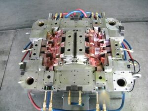
Cooling Line Network

At the point when molds have more than one cooling line, an issue will emerge with regards to how the trim machine administrator will associate the shape to the form temperature regulator. Think about the PC bezel, overlaid with cooling lines as appeared in plastic precision injection mould manufacturers china.

The shape has been furnished with eight cooling lines crossing over the width of the form hole. Confronted with eight cooling line associations, the machine administrator may utilize short hoses to circle the cooling lines as appeared. Such an arrangement has two intensifying issues. To start with, the stream obstruction through the consolidated length of all the cooling lines can be incredibly high, decreasing the coolant stream rates per Eq. .9.16. Second, the form coolant temperature can increment along the length of the cooling circuit at decreased coolant stream rates. Accordingly, a noteworthy temperature differential can emerge from where the coolant enters the shape to where the coolant leaves the form.

Mindful of this issue, numerous if not most decays have coolant manifolds introduced on the trim machine between the shape temperature regulator and the form. The administrator would then be able to utilize longer cooling hoses to separately associate two arrangements of Cooling lines with a short profit circle for the contrary side of the form. Such an equal arrangement is appeared in newest double coler mold parts. This design is very basic since it is basic and gives viable cooling. Notwithstanding, the establishment and expulsion of the form from the machine is muddled by the quantity of lines that must be associated and separated. The high number of hoses and administrator steps additionally improves the probability that the cooling framework might be arrangement mistakenly or fizzle, for example, because of an approximately associated hose.

There is as of now a lot of enthusiasm for the plastics business in lean assembling, which places noteworthy accentuation on decreased cycle intricacy and arrangement times [14-16]. By putting somewhat more in the infusion shape, it is conceivable to decrease the form arrangement time, lessen potential disappointment modes, and improve the form execution. Injection mould manufacturers shows the expansion of two vertical cooling lines interfacing each of the eight flat lines inside the infusion shape; twenty weight plugs have been introduced to hinder the coolant stream at chosen areas. The outcome is that a cooling complex has been planned inward to the form, with the end goal that lone two associations are required. Simultaneously, the cooling consistency is expanded. This inside complex plan has almost no additional expense while conveying both expanded execution and convenience.

Once stopping is viewed as a choice in the steering of cooling lines, a lot more intricate cooling line format become accessible. In the cooling framework plans for the bezel appeared in china standard components for injection mold, the part of the cooling lines situated inside the screen region of the bezel isn’t eliminating any huge warmth. In the event that a two-plate form with a cool sprinter is utilized as appeared in oem/odm automatives injection molding design factory, at that point these cooling lines would cool the sprue and sprinters. For a three-plate or hot sprinter shape, be that as it may, there is no warmth being produced in the focal region of the form cavity. Given that there is no requirement for cooling in the focal point of the form, it is conceivable to course the cooling lines around the outskirts of the part to improve the cooling of the shape hole while lessening oem/odm injection moulding tooling costs and giving a shape that is considerably simpler to work.

This plan gives usability, moderate stream obstruction, and uniform cooling about the whole embellishment.

This article is from http://www.automoldchina.com
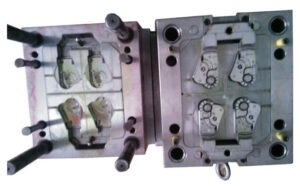
Routing the Cooling Line

When the cooling line distance across, profundity, and pitch have been resolved, the cooling lines can be steered through the form. This steering is of basic significance since it not just effects the expense and nature of the moldings, yet additionally restricts the position of other form segments, for example, ejector pins and jolts. By and large, the shape configuration ought to give at any rate a large portion of a cooling distance across between the outside of the cooling line and the outside of some other form part. This plan imperative is given to keep up the basic trustworthiness of the form while additionally limiting cooling spills during mold activity because of consumption. The concealed zone in Fig. 9.8 speaks to the potential areas in the form where cooling lines might be set.

While the concealed zone of Fig. 9.8 speaks to a huge segment of the shape, the arrangement of cooling lines is additionally obliged by possible obstruction with the form hole, hole embeds, center supplements, ejector return pins, direct pins, sprue bushing, and other shape parts. The past examination for the cup/top shape proposed that the cooling framework configuration use: a cooling line distance across of 6.35 mm, a cooling line profundity of 12.7 mm, and a cooling line pitch of 25.4 mm.

The plan actualized precisely to these proposals is appeared in injection mold company china. This underlying plan is infeasible for some reasons. Maybe the most noteworthy inadequacy in the plan is that a significant number of the cooling lines cross basic form highlights, for example, the sprue bushing or the interface between the pit embeds and the shape plates. There are two unique procedures to determine this issue. One methodology is to amplify the depression embed, center supplement, and related form plates to fit all the cooling lines inside the envelope of the center and pit embeds. This choice is exorbitant since it requires update of the shape, acquisition of a bigger form base, and all the more machining. Notwithstanding, such a plan might be financially legitimized given the more fast and uniform cooling.

An elective methodology is to move the cooling lines further from the form depression while keeping up a similar pitch to profundity proportion for the Cooling lines. The subsequent plan is appeared in china industrial injection mold suppliers. This plan requires less Cooling lines, all of which stay away from the crossing point with other shape parts. While this plan gives helpless cooling execution, it is very normal. An essential favorable position is that the entirety of the cooling lines are straight, yet each C0oling line additionally goes through a solitary shape plate also. Accordingly, the C0oling lines can be machined in a solitary arrangement with no requirement for seals or gaskets. Shockingly, the position of the cooling lines a long way from the form pit will lessen the pace of warmth move and require longer process durations. The pace of warmth move is additionally diminished since the c0oling lines are put in another plate, and there will be a warm contact obstruction related with the warmth stream between the two plates [13].

There is a second critical inadequacy in cooling line format of china industrial injection moulding manufacturers, which originates from the utilization of a straight cooling line with a center of huge stature. The wellspring of cooling is the help plate behind the center addition, a long way from the warmth source beginning from the plastic dissolve in the depression. All things considered, critical temperature varieties will create all through the form and shaped part during cooling.

The anticipated temperature disseminations toward the finish of the trim cycle for the cup are given in Fig. 9.11, in which each shape line speaks to a 2°C change in temperature. Because of the generally profound center, an angle of 6°C exists from the base of the center to the head of the center. The temperature angle in pp joint fitting mould will drive differential shrinkage along the hub of the cup just as differential shrinkage through the divider thickness of the embellishment. The explanation is that the temperature at the head of the center isn’t just 6°C more sizzling than the temperature at the base of the center, but on the other hand is generally 6°C more sultry than the temperature at the contradicting surface on the cavity embed. Three choices for redressing the circumstance incorporate utilizing a profoundly conductive center addition, actualizing a confuse or bubbler, or planning a cooling embed. These distinctive cooling plans are next examined.

This article is from http://www.automoldchina.com/

Cooling Line Depth Choosing

In choosing the last cooling line breadth, the mold creator from oem/odm medical mold design factory ought to consider the manufacturability of the cooling lines and the decay’s norms with respect to cooling plugs, connecting peaks, and hoses. High precision molds made in china gives a few details to commonplace cooling plugs gave by a form segment provider (DME). As seen in the table, the business plugs range from 4.76 to 15.9 mm. The form originator should choose a cooling line distance across that fulfills the above examination and is a standard size.

It ought to be noticed that the above examination is generally fitting for water as the coolant. Ethylene glycol and oil are not as normal by and by because of natural and cost concerns. These non-water coolants are additionally considerably more gooey than water, with the end goal that violent stream isn’t probably going to be accomplished. For laminar, thick stream, the weight drop can be assessed utilizing the recently created Hagen-Poiseuille law with the coolant properties of products made by injection moulding china:

The form fashioner should then choose a suitable cooling measurement to guarantee that the greatest weight drop over the cooling lines doesn’t surpass the ability of the coolant temperature regulator.

After the cooling line width has been resolved, the profundity of the cooling lines must be chosen. From an auxiliary perspective, it is attractive to put the cooling lines a long way from the outside of the form pit. Profound arrangement maintains a strategic distance from the pressure fixations related with the evacuation of material near the surface. For reference, Fig. 9.4 plots the pressure forms for shape plans with cooling line profundities, Hime; equivalent to one cooling line breadth at left and four cooling line measurements at right. It is seen that there are pressure fixations around the cooling line, and the greatness of the pressure, σ, increments essentially as the coling line moves toward the form divider, Stress focus factors have been very much dissected for an assortment of materials, calculations, and burden conditions [10]. For a consistently stacked plate with a gap, the base pressure fixation factor is ordinarily somewhere in the range of 2 and 3 [11]. In any event, when the C00ling lines are set a ways off of four breadths, a pressure focus factor of 2.6 is watched. On the off chance that a shape embed is made of P20, which has a perseverance worry (to maintain a strategic distance from weakness) of 456 MPa. At that point the form must be intended for a most extreme dissolve weight of:

Luckily, this dissolve pressure is about equivalent to the greatest infusion pressure for most trim machines, and is probably not going to be completely communicated to the form hole. The pressure fixation related with cooling lines is huge, and this imperative requires the C0oling line to be put far away from the shape surface in trim applications with high liquefy pressures. In any event, when the cooling lines are set a long way from the hole surface, the pressure focuses still conceivably limit the dissolve pressures with which the shape might be worked. As another model, consider the plan of an aluminum shape with a weakness limit pressure equivalent to 166 MPa. On the off chance that the cooling line profundity is equivalent to one distance across, at that point the pressure focus factor is 3.3, which would permit a most extreme soften weight of only 50 MPa.


This investigation doesn’t forestall the disintegrate from working at higher liquefy pressures, yet just demonstrates that the shape will probably not work for a long existence without creating Cracks radiating from the cooling lines. Stress fixations in molds are talked about in more detail in china mould manufacturing. While the auxiliary contemplations propose that cooling lines ought to be put a long way from the shape surface, the pace of warmth move is augmented by putting the cooling lines as near the surface as could reasonably be expected. The warmth conduction condition expresses that the warm obstruction is direct with the separation between the cooling line and the form surface.

This article is from http://www.automoldchina.com

to Validate the Cooling System

To approve the above cooling investigation, the transient warmth conduction is mathematically reproduced for a trim with a divider thickness of 3 mm. The recreation accepts that the plastic is at first at the liquefy temperature, and that the temperature of the plastic: steel interface at the form divider is consistently at the coolant temperature. As in the past for high-precision molds made in china, the recreation expects that the material is ABS with liquefy, cooling, and discharge temperatures of 239, 60, and 96.7°C, individually. The temperature of the plastic through the divider thickness of the trim is appeared in Fig. 9.2 for different time steps. Toward the beginning of cooling, the temperature of the plastic is at the soften temperature. As indicated by this recreation, the temperature of the plastic at the shape divider quickly drops to the form coolant temperature. As warmth is moved from the plastic to the shape, the temperatures at the external layers decline until at long last the center methodologies the mold coolant temperature.

During cooling, the plastic trim must turn out to be suficiently unbending to withstand discharge powers. Thusly, the cooling time can be assessed from chinese injection moulding companies as the time at which the temperature at the centerline dips under the predefined avoidance temperature. The reproduction results appeared in Fig. 9.2 affirm the past investigative outcomes that the cooling time will be roughly 19 S for a centerline discharge temperature of 97°C.

These outcomes are for an isothermal limit condition at the form divider, implying that plastic at the shape divider promptly drops to the shape coolant temperature. As a general rule, the shape steel can’t pull back warmth so rapidly. Accordingly, the contiguous form steel will increment in temperature. This conduct can be demonstrated utilizing a convective limit condition:

where h。is the delegate heat move coefficient from the soften at the polymer:mold interface to the coolant. Past exploration has demonstrated that the convective warmth move coefficient in trim is on the request for 1000 W/°C, however the default in some embellishment recreations is 5000 W/°C [8]. The mimicked temperature history with a convec tive limit condition is appeared in Fig. 9.3, and is very comparative (though more slow) to the conduct appeared in oem/odm industrial injection moulding design factory. With a convective limit condition, the plastic at the form divider requires extra an ideal opportunity to move toward the shape coolant temperature. This more slow pace of warmth move likewise restricts the cooling at the focal point of the embellishment. On the off chance that the center must arrive at a predefined temperature of 97°C, at that point the cooling time ought to be more like 24 s instead of the 19 s anticipated with an accepted shape divider temperature.

On a side note, there is a typical standard in the plastics business that the cooling time can be assessed as:

The general guideline gave in Eq.9.8 intently coordinates the run of the mill heat conduction investigation gave in Eq. 9.9. While Eq, 9.8 is an amazing rule, it is a smart thought to utilize Eqs. 9.5 and 9.6 to assess the cooling time for the particular application’s plan, material properties, and handling conditions. Likewise, it ought to be noticed that Eq. 9.9 gives a gauge of the cooling time, which is generally 50% of the process duration recently assessed by Eq. 3.5.

Cooling System Design

The cooling system is critical to the financial aspects and activity of the planned mold for the precision plastic injection die factory, but then stays one of the most under engineered systems in infusion molds. Maybe the explanation behind the absence of designing is that the temperature conveyance isn’t evident when embellishment contrasted with abandons identified with stream.

Inappropriately planned cooling systems from china mould manufacturing manufacturers frequently result in any event two unwanted results. To begin with, cooling and process durations are any longer than what might have been accomplished. Second, huge temperature inclinations emerge over the shape, causing differential shrinkage and warpage of the moldings. To work viably, cooling systems must be deliberately intended to deal with the warmth stream all through the shape without causing unjustifiable expense or unpredictability.

In consistent state heat conduction, the warmth move rate, Qconduction , is relative to the warm conductivity, k, and temperature inclination of the shape, dT/dz. There are at any rate two ramifications of this condition. To begin with, heat move rates are relative to the warm conductivity. An exceptionally conductive material like copper or aluminum has a warm conductivity a few times higher than the entirety of the prepares, and ought to have the option to decrease the cooling time in infusion molds. The subsequent ramifications is that a temperature slope is needed to move heat, which likewise implies that warmth move rates can be expanded by drawing the cooling lines nearer to the outside of the shape cavity.

The temperature of the formed parts at the hour of launch is an unpredictable capacity of the shaped part configuration, cooling line plan, material properties, and handling conditions. While high warmth move rates are wanted, an excessively forceful cooling system configuration can really mess quality up. As the cooling lines approach the form pit surface, the warmth move way between the surface and the cooling line turns out to be more straightforward. Therefore, there can be an extraordinary variety in the temperature over the cavity surface except if the cooling lines are additionally positioned exceptionally close together,

At the point when differential shrinkage and warpage happens in the formed parts because of varieties in the temperature of the moldings, the disintegrate frequently must choose the option to run longer process durations and utilize the shape as a cooling installation [1, 2]. By running longer process durations, regularly with higher form coolant temperatures, the decay is diminishing the warmth move rate (and its variety), and afterward permitting the temperature of the shaped plastic to completely equilibrate over the form. The outcome is a cycle any longer than might have been arranged, and which might have been forestalled with a superior cooling system plan absent a lot of extra expense.

A noteworthy issue in the plan of cooling systems is that they frequently struggle with the arrangement of different segments. While setting many, firmly separated cooling lines accommodates quick and uniform cooling, this plan will likewise bring about next to no space in the form to put the ejector systems, sprinters, latches, and other shape segments. Thus, the mold designer from china mould design services ought to endeavor to course cooling lines that equal the math of the shape holes. A littler cooling line distance across, while more hard to machine and moving less warmth, may lesserly affect close by segments and take into account the utilization of numerous lines to accomplish more uniform cooling.

This article is from http://www.automoldchina.com
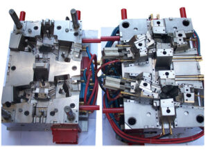
Gate Dimension

After the shear rate, pressure drop, and entryway freeze time have been determined for an underlying plan, the sort and measurements of the door can be changed by injection mold services china to improve the plan. For tasteful and de gating purposes, littler door sizes are wanted. As the past models have appeared, in any case, unreasonable shear rates may direct the utilization of bigger door sizes. These shear rate computations are needy upon an accepted stream rate, and this stream rate won’t be known until after the decay has improved the cycle with the actualized shape. Therefore, the shape planner should accept a sensible stream rate for investigation, select a sort of door that can be augmented, and indicate measurements that are”steel safe.” thusly, the size of the entryways can be promptly expanded to decrease shear rates varying.

Door measurements are may likewise be acclimated to change the weight drops and stream rates at various entryways. Such fine – tuning may assist with adjusting the soften stream between numerous holes, or to modify the stream rates and weave line areas inside a multigated cavity. The degree of the adjusting that can be accomplished through door configuration is incredibly restricted because of the little size of the entryway. To achieve huge changes in stream, china high-precision mould suppliers know that the door measurements must differ by such critical sums that the shear rates and entryway freeze times will shift significantly between entryways, causing unintended outcomes. Thus, it might be wanted to change the components of the sprinters or to utilize a unique stream control innovation for dissolve control.

Entryway measurements are frequently acclimated to improve the dimensional control of moldings by china industrial injection mold manufacturers. At the point when the door hardening time is altogether not exactly the pressing time required by the soften in the hole, at that point inordinate volumetric shrinkage may happen. There are four methodologies that are utilized to decrease the volumetric shrinkage. The most well-known methodology utilized by the disintegrate is to force a high pressing weight before the entryway freezes, with the end goal that the leftover soften pressure in the hole will be assuaged as the liquefy contracts. Lamentably, this methodology can prompt exorbitant glimmering and additionally remaining burdens. Thus, a subsequent regular methodology is to expand the breadth or thickness of the door to build the cementing time and give pressing at more moderate dissolve pressures. A third methodology is to utilize an alternate (regularly molecule filled) material with lower volumetric shrinkage to accomplish the ideal part measurements. A fourth, and frequently kept away from, approach is to adjust the shape to lessen the ostensible thickness of the trim.

The door configuration measure incorporates the choice of the kind of entryway and the cautious determination of the entryway measurements to adjust feel, shear rates, pressure drops, and pressing occasions. The determination of the entryway type will basically be dictated by the past particular of the form type (two-plate, three plate, or hot sprinter), the need to achieve a specific sort of stream in the door or potentially pit, lastly by the longing to give a vigorous and completely programmed shaping cycle. The advancement of door measurements is driven by the tradeoff between little entryway estimates (that accommodate improved style and simplicity of de gating) and enormous entryway measures (that accommodate lower shear rates and weight drops). On the off chance that the detail of the door measurements is dubious, at that point the shape architect ought to use littler entryway measurements since they can be all the more promptly expanded in size whenever required in the wake of trim preliminaries.

This article is from http://www.automoldchina.com.