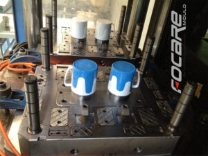
At the point when the plastic liquefy is injected into the mold hole at high weight by china injection mould maker, huge clip power is needed to keep the mold shut so the dissolve doesn’t get away from the mold cavity. Since the cinch power is relative to the extended territory of the mold cavities, the brace power increments relatively with the number of shape cavities over the splitting plane. In any case, on the off chance that the pits are”stacked” one on head of another, at that point the clip power used to close one lot of cavities can likewise be utilized to close any arrangements of pits that are in the stack.
One such stack mold configuration from china precision molds manufacturers, which was intended to shape two vinyl records with the clasp power and process duration typically used to mold one vinyl record. In this plan, two arrangements of stampers are mounted between an internal plate, 12, and two external plates, 14 and 16; the inward plate, 12, is guided by course, 20. The dissolve streams from the spout, 54, of the embellishment machine through broadened sprue, 40, to two arrangements of holes where the records are framed. After the plastic sets, the dissolve shut-off pole, 65, is incited to seal the sprue bay, 51, with the shut-off, 66. This activity additionally associates the sprue, 40, to the chute, 64, to such an extent that the sprue might be taken from the moldings with initation of the sprue take out bar, 75. The shaped records are then catapulted subsequent to withdrawing the sprue take out pole and opening the mold.

There are two in-sufficiency in the mold plan. To begin with, the stack shape requires the arrangement of a sprue, which is scrap. Second, the soften stream to the two holes isn’t adjusted, because of the extra length of the sprue to one side pit. Both these defliciencies are settled in present day stack mold plans that use hot sprinter frameworks.
In this plan of plastic injection molding services china, a focal moving plate, 56, houses two arrangements of depressions, 60, on contradicting separating planes, 62 and 64. A hot complex, 65, conveys the polymer soften to the pits through the sprinter, 70, and ensuing drops. The plan utilizes tw0 single hub valve entryways to convey the liquefy from the trim machine spout, 17, over the splitting plane, 62, and to the complex, 65. During filling and pressing phases of the trim cycle, the actuators, 50 and 54, withdraw the valve pins, 24, to convey the liquefy from the n0zzle to the complex. Something else, the valve pins seal the feed framework during the plastication, Cooling, and mold reset stages.
While the stack shape configuration expands the stack stature and intricacy of the mold, it empowers the embellishment of two arrangements of pits with a similar process duration and clasp power as a solitary arrangement of cavities. Besides, the stream to the two arrangements of holes is totally ba speared and there is no material waste related with the hot sprinter feed framework. Given the huge part cost decreases managed by this sort of stack mold configuration, stack molds are now very normal with two, three, and four degrees of depressions. Unmistakably, the stack shape configuration requires the cautious adjusting of potential preparing cost reserve funds with issues identified with speculation, upkeep, shading change, stack stature, and injection volume by oem injection mold factory.
This article is from http://www.automoldchina.com/.