Feed System & Runner

The plan of the feed system is basic to infusion shaping yet is regularly dubious. One basic issue is the ability of an accessible trim machine to fill the shape with a material whose stream attributes are obscure. Then again, there might be vulnerability with regards to the specific liquefy stream rates and weights that are needed to appropriately adjust a family mold or complex multi-gated part / injection molded part.

In questionable circumstances, the form architect ought to determine feed system measurements that are”steel safe,”which implies that the plan should require the expulsion of less shape steel than may eventually be required. Accordingly, the shape architect may wish to adjust the feed system measurements down a couple of standard sizes. Thusly, the shape originator will force a more prominent weight drop and utilize less material than anticipated by the investigation. There is a sensible possibility that the modest feed system may work appropriately. Besides, on the off chance that the feed system requires at least one changes, at that point the”steel safe” plan might be effectively machined with bigger runner sizes to improve the form execution.

Mold manufacturing factory suggests a”steel safe” runner plan if the examination showed an ideal distance across of 4.6 mm for a chilly runner. On the off chance that the feed system examination brought about a runner distance across of 4.6 mm, at that point the shape creator may indicate a measurement of 4.5 mm or even 4 mm for a “steel safe” plan. By correlation, if the form fashioner had gathered together to 5 mm, the plan would have given a lower pressure drop yet expended pointless material all through the shape’s whole lifetime. Moreover, in the event that the disintegrate wanted to lessen the 5 mm breadth, at that point the form would require more broad adjust including pocket processing of the old feed system, the assembling and fitting of a properly measured supplement, welding or potentially the expansion of latches, lastly the arrangement of the new, littler feed system. While this model zeroed in on steel safe plan of cold runners, the steel safe idea is additionally relevant to hot runner plans.
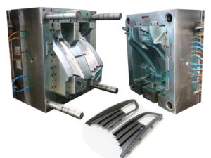
As recently portrayed by oem/odm injection mold factory, the most widely recognized sorts of feed systems are cold runners and hot runners. The two kinds of feed systems have detriments. With cold runners, there is impressive material waste related with the arrangement of the feed system just as the potential for broadened process durations. With hot runners, there is the extra expense and intricacy related with the temperature control systems, just as the potential for temperature varieties and shading change issues.

As an option for high precision mould china in contrast to both cold runner and hot runner designs for injection molding china, the protected runner was planned trying to kill these impediments. The plan design is fundamentally the same as a three-plate shape with a runner segment 15, a cavity segment 16, and center areas 17. The runner format is likewise comparable with a sprue 19 passing on the liquefy through the plate thickness to essential and optional runners 18 that pass on the soften over the splitting plane to a second arrangement of sprues, 22 and 23, which pass on the dissolve down to the shape depressions. Contrasted with a customary three-plate shape, be that as it may, all fragments of the feed system are intentionally intended to have huge distances across. In expansion, the runner segment 15 is made sure about to the depression area 16 and doesn’t open at all during ordinary embellishment.

During the trim cycle, the soften is infused from the spout of the embellishment machine and totally flls the feed system. A skin, 18a and 18b, promptly shapes on the outside of the runners. Be that as it may, the set skin doesn’t completely engender all through the runner, since the warm conductivity of plastic is exceptionally low and each forming cycle passes on warmed polymer dissolve from the trim machine all through the feed system.

Accordingly, the measurement of the liquid center remains almost predictable during the trim cycle. Thusly, the protected runner can be worked as a hot runner, though with no warmers, thermocouples, or temperature regulators. The shading change issue is settled by eliminating the completely hardened feed system with the arrival of runner area 15 from the cavity segment 16. This article is from http://www.automoldchina.com/
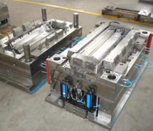
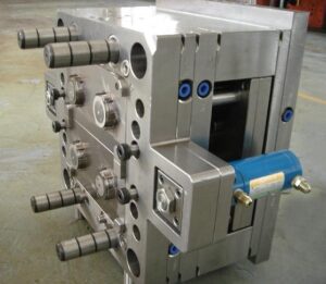
Mold Base Size

It’s a common information for China high precision mold manufacturers that to get the right mold base for the production should take different conflicts into consideration. Sometimes the result may come out disappointed if we miss some small parts, which may lead to rework all moulding parts. The size of the mold base is resolved essentially by the region needed to oblige all the hole embeds per the planned depression format for china precision plastic injection mold factory. An essential issue for china precision injection plastic parts factory, nonetheless, is the potential for strife between the situations of the cavities and other mold parts, (for example, pioneer pins, manage bushings, and others). Besides, there is the potential for strife between cavity emotionally supportive networks, (for example, cooling lines, ejector pins, uphold pillars, and so forth.) and other mold parts, (for example, pioneer pins, direct bushings, and others). Due to these conflicts, mold bases are frequently estimated bigger than what might initially be thought of.

The concealed region in Fig. 4.21 speaks to the usable zone of the splitting plane into which the center and hole additions can be put. Ejector return pins are situated to one side and right of this region, while control pins and attachment head top screws are situated over this region. A dimensional recompense equivalent to in any event one-portion of every part’s distances across is given between the mold cavity and the encompassing segments to keep away from exorbitant worry during the mold’s activity.

Given the cavity design and its mathematical envelope, a mold base with an achievable length and width is chosen. Standard mold bases from oem/odm automotives mould factory are broadly accessible from 200 mm up to 1000 mm on a side. While determining a mold base, it is additionally important to indicate the tallness of the”A”plate, the stature of the”B”plate, the tallness of the help plate,”S,” and the separation of the ejector travel,”E”. The absolute stack stature is characterized as the good ways from the base of the back clip plate to the head of the top clasp plate.

Regarding mold base choice, the tallness of the”A”and”B”plates are separately coordinated to the stature of the hole and center embeds as recently examined. The stature of the help plate, “S,” is typically decided from the mold base provider dependent on the tallness of the”A”and”B”plates, however the tallness of the help plate can be unique arranged to shifting measurements. The movement of the ejector plate ought to be chosen to discharge the part from the mold. Frequently, the ejector go is set to be equivalent to the profundity of the molded part. From the ejector travel, the tallness of the ejector lodging, dimension”C, is allocated by the mold base provider.

China automatives injection overmould manufacturers know it clearly that while choosing a mold base, it is additionally important to indicate an opening breadth for the sprue. This measurement is of lesser significance since the sprue bushing might be supplanted or machined, or the embellishment machine nozzle changed, to coordinate the sprue to the nozzle as later examined.

This article is from http://www.automoldchina.com/.

Mold External Look

It’s critical for china plastic mould makers to have the mold clear and right external look before any quotation or production. An isometric perspective on a two-plate form is given in Fig. 1.4. From this view, it is seen that a form is built of various plates shot along with attachment head top screws. These plates regularly incorporate the top brace plate, the cavity embed retainer plate or”A”plate, the center supplement retainer plate or”B”plate, a help plate, and a back clip plate or ejector lodging. Some form parts are alluded to with numerous names. For example, the”A” plate is here and there alluded to as the pit embed retainer plate, since this plate holds the depression embeds. As another model, the ejector lodging is additionally here and there alluded to as the back clip plate, since it clasps to the moving platen situated towards the back of the embellishment machine. In some form structures, the ejector lodging is supplanted with a detachable back clasp plate of uniform thickness and two equal ejector “rails”that supplant the side dividers of the integral”U”- molded ejector lodging. This elective back brace plate configuration requires more parts and form making steps, however can give material cost reserve funds just as shape plan adaptability. Also this should be judged if fit for the chinese injection molding machines.


The form delineated in Fig. 1 .4 is alluded to as a”two plate form” since it utilizes just two plates to contain the polymer soften. Form plans may fluctuate altogether while playing out similar capacities. For instance, some form structures incorporate the”B” plate and the help plate into one extra-thick plate, while other shape plans may coordinate the”A”plate and the top clip plate. As recently referenced, some form plans may separate the ejector lodging, which has a”U”- molded profile to house the launch instrument and clipping openings, into a back clasp plate and tall rails (otherwise called risers). The utilization of a coordinated ejector lodging as appeared in Fig.1.4 accommodates a minimal shape structure, while the utilization of independent back clip plate and rails accommodates more noteworthy plan adaptability. High precision plastic making mould china need to get the clear detailed external view carefully so as to arrange the production.


To hold the form in the injection shaping machine, toe cinches are embedded in spaces adjoining the top and back brace plates and in this manner dashed to the fixed and moving platens of the embellishment machine. A finding ring, typically found at the focal point of the form, intently mates with an opening in the embellishment machine’s fixed platen to adjust the channel of the shape to the trim machine’s spout.


The opening in the trim machine’s fixed platen can be seen in Fig. 1.1 around the embellishment machine’s spout. The utilization of the finding ring is important for at any rate two reasons. To begin with, the channel of the dissolve to the shape at the form’s sprue bushing must mate with the outlet of the liquefy from the spout of the trim machine. Second, the ejector knockout bar(s) incited from behind the movingļ¼Œplaten of the trim machine must mate with the ejector arrangement of the shape.


The oem/odm largest plastic injection molding companies in China have its own ability that embellishment machine and shape providers have created standard finding ring particulars to encourage form to-machine similarity, with the most well-known finding ring width being 100 mm (4 in). At the point when the trim machine’s moving platen is incited, all plates connected to the back clasp plates will be correspondingly impelled and cause the form to isolate at the splitting plane. At the point when the form is shut, control pins and bushings are utilized to intently find the “An” and the “B”plates on isolated sides of the splitting plane, which is critical to the essential shape capacity of containing the soften. Ill-advised structure or development of the form segments may cause misalignment of the”A” and”B”plates, low quality of the shaped parts, and quickened wear of the injection shape.

This article is from http://www.automoldchina.com/.