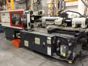
Minimize the Mold Stress

Injection molds are exposed to elevated levels of weight from the warmed polymer dissolve. At the point when this weight is coordinated across the surfaces of the form cavities, powers result that regularly range from tens to thousands of tons. The foundational layout of the form should be adequately powerful to withstand these powers, yet additionally to do as such while delivering great shaped items.

For the chinese injection moulding companies to build up a hearty foundational layout, the shape originator ought to comprehend the connections between the weights, powers, and stresses in an injection form. China high-precision mould suppliers shows the run of the mill stream of stresses through the form, platens, and tie-bars. During embellishment, the dissolve pressure is applied against all surfaces of the form pits. This weight brings about both compressive and shear stresses in the depression embeds, center embeds, and backing plates. This blended condition of pressure is shown by the inclining bolts in china industrial injection mold manufacturers. The embellishment machine’s platens are likewise under a critical condition of adapting to move the powers to the tie bars, which are in strain.
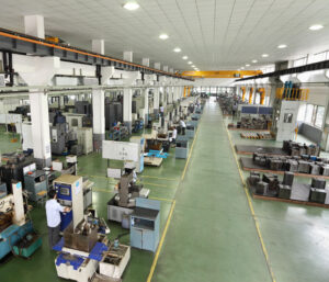
When all is said in done, the form fashioner wishes to give a foundational layout to the shape that will neither break because of exhaustion across many trim cycles, unnecessarily divert under burden, nor won’t be excessively cumbersome or costly. These destinations can be unequivocally expressed as:

■Minimize the pressure,

■Minimize diversion, and

■Minimize cost.

Every one of these targets is next quickly examined after which the itemized examination and plan of molds are introduced.

The condition of pressure fluctuates essentially between the moving and the fixed sides of the form. For most forms, the depression embeds are straightforwardly upheld by the top brace plate and the fixed platen. Thusly, the depression embeds are for the most part in a condition of unadulterated pressure so next to no out of plane bowing happens. On the moving side, be that as it may, the pocket needed to house the ejector get together offers no help for the center supplements. Therefore, the center embeds and backing plates should send the heap by means of both compressive and shear stresses, which will in general bring about critical plate bowing.

Mould manufacturers factory plots the anticipated von Mises pressure in a hot sprinter form for the PC bezel when the surfaces of the shape depression are exposed to 150 MPa of dissolve pressure.’ The von Mises pressure, OMises, is a generally utilized basis to foresee disappointment. The cutoff stress is normally dictated by two essential concerns. The main concern is that the pressure ought not be so high in order to plastically misshape the form. At the point when a material is exposed to pressure, it will misshape or strain. For most materials, the measure of disfigurement is relative to the applied pressure. The proportion of pressure to strain is identified with the flexible modulus, E. where ε is the strain that outcomes from an applied pressure, σ. A material with a higher flexible modulus will in general misshape less given an applied pressure.

This article is from http://www.automoldchina.com/
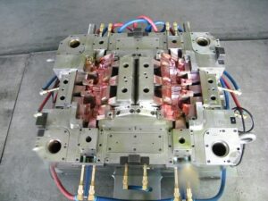
to Validate the Cooling System

To approve the above cooling investigation, the transient warmth conduction is mathematically reproduced for a trim with a divider thickness of 3 mm. The recreation accepts that the plastic is at first at the liquefy temperature, and that the temperature of the plastic: steel interface at the form divider is consistently at the coolant temperature. As in the past for high-precision molds made in china, the recreation expects that the material is ABS with liquefy, cooling, and discharge temperatures of 239, 60, and 96.7°C, individually. The temperature of the plastic through the divider thickness of the trim is appeared in Fig. 9.2 for different time steps. Toward the beginning of cooling, the temperature of the plastic is at the soften temperature. As indicated by this recreation, the temperature of the plastic at the shape divider quickly drops to the form coolant temperature. As warmth is moved from the plastic to the shape, the temperatures at the external layers decline until at long last the center methodologies the mold coolant temperature.

During cooling, the plastic trim must turn out to be suficiently unbending to withstand discharge powers. Thusly, the cooling time can be assessed from chinese injection moulding companies as the time at which the temperature at the centerline dips under the predefined avoidance temperature. The reproduction results appeared in Fig. 9.2 affirm the past investigative outcomes that the cooling time will be roughly 19 S for a centerline discharge temperature of 97°C.

These outcomes are for an isothermal limit condition at the form divider, implying that plastic at the shape divider promptly drops to the shape coolant temperature. As a general rule, the shape steel can’t pull back warmth so rapidly. Accordingly, the contiguous form steel will increment in temperature. This conduct can be demonstrated utilizing a convective limit condition:

where h。is the delegate heat move coefficient from the soften at the polymer:mold interface to the coolant. Past exploration has demonstrated that the convective warmth move coefficient in trim is on the request for 1000 W/°C, however the default in some embellishment recreations is 5000 W/°C [8]. The mimicked temperature history with a convec tive limit condition is appeared in Fig. 9.3, and is very comparative (though more slow) to the conduct appeared in oem/odm industrial injection moulding design factory. With a convective limit condition, the plastic at the form divider requires extra an ideal opportunity to move toward the shape coolant temperature. This more slow pace of warmth move likewise restricts the cooling at the focal point of the embellishment. On the off chance that the center must arrive at a predefined temperature of 97°C, at that point the cooling time ought to be more like 24 s instead of the 19 s anticipated with an accepted shape divider temperature.

On a side note, there is a typical standard in the plastics business that the cooling time can be assessed as:

The general guideline gave in Eq.9.8 intently coordinates the run of the mill heat conduction investigation gave in Eq. 9.9. While Eq, 9.8 is an amazing rule, it is a smart thought to utilize Eqs. 9.5 and 9.6 to assess the cooling time for the particular application’s plan, material properties, and handling conditions. Likewise, it ought to be noticed that Eq. 9.9 gives a gauge of the cooling time, which is generally 50% of the process duration recently assessed by Eq. 3.5.

Filling Patterns

Filling patterns can be promptly anticipated utilizing the lay level examination strategy and are valuable to comprehend the conduct of the liquefy in filling the shape, finding doors, recognizing sew line areas, and aiding different parts of mold plan by pom moulding parts manufacturers china. Examination will be performed for a five-sided compartment with a width, length, and tallness of 100 mm, 160 mm, and 60 mm, separately.

Accepting that a two-plate form will be utilized by the mould manufacturers factory, the holder will be gated at the edge of a side divider, To foresee the filling designs, the sides of the compartment are”cut” at the corners and the side dividers collapsed down to make a lay level. The door area is next recognized. The stream will radiate from the entryway, creating a round liquefy front. In that capacity, a curve might be drawn from the entryway speaking to the situation of the soften at a given point in time.

Each bend relates to the area of the liquefy front at an alternate time step; the separation between the curves is equivalent to the straight dissolve speed times the time step. While the liquefy area at the first run through advance is right, the soften will hit the contiguous side divider before the second’s over time step. All things considered, it is important to draw extra curves on these contiguous side dividers mirroring the situation of the soften stream at different time steps. To effectively foresee the stream conduct, the investigation must keep up a similar stream obstruction between the liquefy streaming in the different segments of the form. This can be practiced by making a “phantom”gate and keeping up a similar stream lengths from this “apparition” entryway as from the genuine door.

For each time step, which has been considered by injection molding service china, the length of stream is expanded and a curve of comparing sweep is drawn. Meeting bends comparing to a similar time step are then tended to. The stream is progressed with more ghost doors included varying until the stream all through the whole lay level is made.

High-precision molds made in china shows this liquefy front forecast measure and the subsequent soften front areas for the holder. It is seen that the stream races around the side dividers and will shape a weld line and a gas trap as an afterthought divider inverse the entryway.

This wonder, known as”race – following,” is very regular in shaped parts and can happen when the length of stream around the border of the embellishment is not exactly the length of stream over the center line of the part.

For this situation, race-following happened in light of the fact that the 60 mm profundity of the holder is more than one a large portion of the 100 mm width of the compartment. While the weld line isn’t alluring, a gas trap on a side divider, for example, appeared in china high-precision mould suppliers is particularly risky since it is hard to vent. In that capacity, the caught air will probably combust, causing a consume imprint to show up at this area.

This article is from http://www.automoldchina.com/