Minimize the Mold Stress

Injection molds are exposed to elevated levels of weight from the warmed polymer dissolve. At the point when this weight is coordinated across the surfaces of the form cavities, powers result that regularly range from tens to thousands of tons. The foundational layout of the form should be adequately powerful to withstand these powers, yet additionally to do as such while delivering great shaped items.

For the chinese injection moulding companies to build up a hearty foundational layout, the shape originator ought to comprehend the connections between the weights, powers, and stresses in an injection form. China high-precision mould suppliers shows the run of the mill stream of stresses through the form, platens, and tie-bars. During embellishment, the dissolve pressure is applied against all surfaces of the form pits. This weight brings about both compressive and shear stresses in the depression embeds, center embeds, and backing plates. This blended condition of pressure is shown by the inclining bolts in china industrial injection mold manufacturers. The embellishment machine’s platens are likewise under a critical condition of adapting to move the powers to the tie bars, which are in strain.
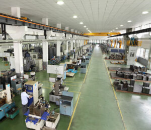
When all is said in done, the form fashioner wishes to give a foundational layout to the shape that will neither break because of exhaustion across many trim cycles, unnecessarily divert under burden, nor won’t be excessively cumbersome or costly. These destinations can be unequivocally expressed as:

■Minimize the pressure,

■Minimize diversion, and

■Minimize cost.

Every one of these targets is next quickly examined after which the itemized examination and plan of molds are introduced.

The condition of pressure fluctuates essentially between the moving and the fixed sides of the form. For most forms, the depression embeds are straightforwardly upheld by the top brace plate and the fixed platen. Thusly, the depression embeds are for the most part in a condition of unadulterated pressure so next to no out of plane bowing happens. On the moving side, be that as it may, the pocket needed to house the ejector get together offers no help for the center supplements. Therefore, the center embeds and backing plates should send the heap by means of both compressive and shear stresses, which will in general bring about critical plate bowing.

Mould manufacturers factory plots the anticipated von Mises pressure in a hot sprinter form for the PC bezel when the surfaces of the shape depression are exposed to 150 MPa of dissolve pressure.’ The von Mises pressure, OMises, is a generally utilized basis to foresee disappointment. The cutoff stress is normally dictated by two essential concerns. The main concern is that the pressure ought not be so high in order to plastically misshape the form. At the point when a material is exposed to pressure, it will misshape or strain. For most materials, the measure of disfigurement is relative to the applied pressure. The proportion of pressure to strain is identified with the flexible modulus, E. where ε is the strain that outcomes from an applied pressure, σ. A material with a higher flexible modulus will in general misshape less given an applied pressure.

This article is from http://www.automoldchina.com/
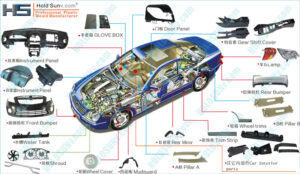
Filler

The consequences of electric cars plastic accessories vacuum forming manufacturers china are plotted with a similar scale for shrinkage concerning plastic injection moulded components china, and show that the straight shrinkage has moved toward that of the fourgated form plan without added cost. Sadly, barely any decays influence the capacities of pack compel profiling to amplify part quality.

Numerous shapeless plastics have shrinkage rates on the request for 0.5 %. Nonetheless, semicrystalline polymers can show altogether higher shrinkage rates. For instance, the particular volume for an acetal (Delrin 500) is plotted in oem/odm 2 shot injection moulding factory. Since acetal is a semi-crystalline polymer, there is a huge change in the particular volume when the polymer advances from a firmly stuffed semi-crystalline strong to an approximately pressed indistinct liquefy. This expansion in the particular volume can offer ascent to critical volumetric shrinkage and high shrinkage rates contrasted with undefined materials. For this equivalent explanation, the shrinkage pace of semi-crystalline plastics is profoundly reliant on the coolant temperature and pace of cooling.

Figure 10.17 demonstrates that the particular volume toward the finish of pressing is 0.77. The material at that point cools and changes to a semi-crystalline strong with a particular volume at room temperature equivalent to 0.69. The overall change in the volumetric shrinkage is 0.90. This compares to a direct shrinkage of 3.5 %. Embellishment applications with such high shrinkage rates will in general be more difficult to control to tight resistances because of their expanded affectability to handle conditions. Besides, colorants can go about as nucleators for semi-crystalline polymers, with the end goal that the shrinkage of hued and flawless variants of exactly the same evaluation may display diverse shrinkage conduct [13]. Best practices for form configuration including reproduction, planning steel safe, and altering the shape and model trim can be utilized to tune the shrinkage of semi-crystalline polymers to acquire tight resistances. At whatever point conceivable, form originators ought to analyze comparative trim applications and evaluate their real shrinkage rates.

To a huge degree, fillers can be utilized to impact the measure of shrinkage that a material shows. The most well-known fillers are mica, glass globule, glass fiber, carbon dark, and elastic. The thickness and coefficient of warm development for these materials are given in injection mold services china.

It tends to be seen from china injection mold maker that, except for elastic (which is normally added as an effect modifier), all the fillers have an exceptionally low coefficient of warm development (on the request of5.10-6 m/m°C) contrasted with that of plastic (on the request for 100. 10-6 m/m°C). Consequently, the expansion of at least one fillers to a perfect tar can be utilized to decrease the polymer’s volumetric shrinkage and in this manner increment the formed part measurements; the adjustment in shrinkage will in general fluctuate relatively with the fllr’s volumetric stacking [14]. The investigation of flled pitches for which the PvT conduct isn’t accessible can be led with the PvT model for the unfilled sap as indicated by the examination model gave in injection mould tooling china.

This article is from http://www.automoldchina.com/
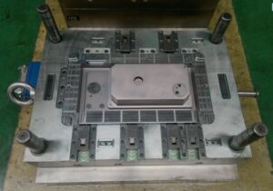
Fan Gate

The fan gate can be considered as another variation of the edge entryway, in which the width of the fan entryway at the embellishment exceeds the breadth of the runner. One fan entryway configuration is appeared. In this plan of china high-precision mould suppliers, the width of the fan gate has been chosen to stay away from exorbitant shear rates when the liquefy streams into the depression at a high volumetric stream rate. Given the huge width of most fan entryways, the feed framework is ordinarily eliminated by a fueled gate shaper, responding saw, or switch.

One regular utilization of fan gates for the pom moulding parts manufacturers china is to give a direct liquefy stream from the entryway rather than the outspread stream that will result with the previ0us gate plans. A straightforward formed plaque application with a fan entryway is appeared. For this plan to be powerful, two rules must be met. To start with, the fan gate must traverse the width of the trim across which straight low is wanted. Second, the Ilow opposition over the width of the fan gate must be unimportant. Different fan entryway calculations have been created to modify the stream rates into the hole over the width of the fan gate. The plan is normal, and comprises of a basic space between the roundabout segment of the runner and the rectangular segment of the shape hole.

While fan entryways are viable, another option is the blaze gate or film gate. The word”flash” suggests a dissolve course through a dainty area. In like manner, the glimmer entryway comprises of a thick roundabout area that is nearby a slight rectangular segment. During embellishment, the soften will continue from the runner into the thick round area. The slim nearby area will cause the soften stream to slow, cool, and conceivably freeze while the liquefy fills the thick segment. When the dissolve hits the finish of the thick area, the liquefy weight will at that point increment essentially and power the solidified material in the meager segment to stream. Since the stream obstruction along the thick area is little contrasted with the stream opposition over the slim segment, the blaze entryway gives an almost straight dissolve stream to the depression over its width.

The idea of the blaze gate can be stretched out to a barrel shaped math to give a straight dissolve stream without sew lines. In this plan, a strong thick”diaphragm”is used to pass on the liquefy from the sprue to the internal outskirts of the form hole. A more slender entryway segment is then used to guarantee a uniform hole filling and furthermore aid the expulsion of the stomach from the embellishment. Despite the fact that the math of the stomach entryway is barrel shaped, the investigation of the shear A blaze gate can commonly be eliminated by an administrator without the requirement for power helped cutters by consistently flexing the embellishment utilizing the glimmer entryway as a pivot.

Because of the math of the stomach gate, notwithstanding, power apparatuses or a punch press are ordinarily required for de-gating. Both the blaze and the stomach entryways will leave an observer line, so it is wanted to limit the thickness of the gate; average thicknesses are on the request for 0.2 to 0.6 mm, or around 33% the thickness of the formed part. The math and slenderness of these entryways may appear to be to force over the top shear rates and weight drops upon the dissolve. In any case, these gates’ enormous widths will bring about moderately low direct dissolve speeds even at high volumetric stream rates. Thus, these gates can be viably intended to give moderate shear rates and weight drops.