Perseverance Stress

Weariness is a surely known instrument, and the conduct of different materials has been portrayed through cyclic pressure testing to a milion cycles or more. When all is said in done, the quantity of cycles that a shape can withstand will diminish with the applied pressure. Medical instrument mould made in china plots the normal number of cycles before disappointment because of weakness as a component of the forced pressure for P20 steel [2] and aluminum 6061T6 [3]. This information is by and large alluded to as”sn”curves where the”s” infers pressure and the”n”implies number of cycles. The”endurance stress” is characterized as the pressure at which a hypothetically limitless number of pressure cycles can be applied without disappointment. For most prepares, the perseverance stress is around one-a large portion of the yield pressure. For P20, the perseverance stress is roughly 450 MPa,The information in china injection mold maker demonstrate that 6061-T6 has a much lower perseverance stress than P20. There are two significant contrasts in the practices of aluminum and steel. To begin with, the s-n bend for aluminum has a more noteworthy slant than that for steel.

Second, aluminum doesn’t show a perseverance stress limit. All in all, the kept cycling of any weight on aluminum will at last reason disappointment because of weakness. Hence, the shape architect working with aluminum should cautiously choose the cutoff stress as per the ideal number of embellishment cycles. In the event that a form embed made of aluminum 6061-T6 is to be utilized for under 1000 embellishment cycles, at that point the shape fashioner may choose a cutoff stress equivalent to the yield pressure of 483 MPa. On the off chance that roughly 10,000 trim cycles are normal, at that point as far as possible pressure drops to 240 MPa. In the event that the shape is to be worked for up to 1,000,000 trim cycles, at that point the cutoff stress should be set to 110 MPa.

To sum up, the breaking point pressure is specified as indicated by whether issues identified with yielding or weariness will overwhelm during the shape’s activity. In the event that the shape is to be intended for a low number of embellishment cycles, at that point the cutoff stress can be set to the yield pressure and planned utilizing a wellbeing factor or a most dire outcome imaginable. In the event that the shape is to be worked for countless trim cycles, at that point the perseverance stress should be utilized as the cutoff stress. These information are accommodated some basic form materials in Appendix B.

While inordinate burdens in the form parts can make harm the shape, excessive form redirection is a considerably more noteworthy worry in many trim applications. The essential explanation is that exorbitant shape redirection can cause blazing at the splitting lines between the center and pit embeds. In close resilience applications, shape diversion can likewise cause part measurements to be out of specification. In that capacity, the form configuration might be driven more by the need to limit redirection as opposed to limiting pressure.

This article is from http://www.automoldchina.com/
Cooling System Design

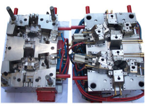
The cooling system is critical to the financial aspects and activity of the planned mold for the precision plastic injection die factory, but then stays one of the most under engineered systems in infusion molds. Maybe the explanation behind the absence of designing is that the temperature conveyance isn’t evident when embellishment contrasted with abandons identified with stream.

Inappropriately planned cooling systems from china mould manufacturing manufacturers frequently result in any event two unwanted results. To begin with, cooling and process durations are any longer than what might have been accomplished. Second, huge temperature inclinations emerge over the shape, causing differential shrinkage and warpage of the moldings. To work viably, cooling systems must be deliberately intended to deal with the warmth stream all through the shape without causing unjustifiable expense or unpredictability.

In consistent state heat conduction, the warmth move rate, Qconduction , is relative to the warm conductivity, k, and temperature inclination of the shape, dT/dz. There are at any rate two ramifications of this condition. To begin with, heat move rates are relative to the warm conductivity. An exceptionally conductive material like copper or aluminum has a warm conductivity a few times higher than the entirety of the prepares, and ought to have the option to decrease the cooling time in infusion molds. The subsequent ramifications is that a temperature slope is needed to move heat, which likewise implies that warmth move rates can be expanded by drawing the cooling lines nearer to the outside of the shape cavity.

The temperature of the formed parts at the hour of launch is an unpredictable capacity of the shaped part configuration, cooling line plan, material properties, and handling conditions. While high warmth move rates are wanted, an excessively forceful cooling system configuration can really mess quality up. As the cooling lines approach the form pit surface, the warmth move way between the surface and the cooling line turns out to be more straightforward. Therefore, there can be an extraordinary variety in the temperature over the cavity surface except if the cooling lines are additionally positioned exceptionally close together,

At the point when differential shrinkage and warpage happens in the formed parts because of varieties in the temperature of the moldings, the disintegrate frequently must choose the option to run longer process durations and utilize the shape as a cooling installation [1, 2]. By running longer process durations, regularly with higher form coolant temperatures, the decay is diminishing the warmth move rate (and its variety), and afterward permitting the temperature of the shaped plastic to completely equilibrate over the form. The outcome is a cycle any longer than might have been arranged, and which might have been forestalled with a superior cooling system plan absent a lot of extra expense.

A noteworthy issue in the plan of cooling systems is that they frequently struggle with the arrangement of different segments. While setting many, firmly separated cooling lines accommodates quick and uniform cooling, this plan will likewise bring about next to no space in the form to put the ejector systems, sprinters, latches, and other shape segments. Thus, the mold designer from china mould design services ought to endeavor to course cooling lines that equal the math of the shape holes. A littler cooling line distance across, while more hard to machine and moving less warmth, may lesserly affect close by segments and take into account the utilization of numerous lines to accomplish more uniform cooling.

This article is from http://www.automoldchina.com

Mould Customization

The hole completing cost, Cavity. inisting; is additionally a huge cost driver speaking to 5 to 30% of the complete form cost. The completing expense is the result of the time needed to complete the depression surface territory, tcavity fnishing; and the completing work rate, Rrinishing rate.

The completing time is a component of every zone of the part to be done by plastic molding services china, A section surface; isolated by the rate at which the zone is done, Ri。cavity_ wrapping up.

Since the completing rate relies upon the surface completion and surface to be applied, the utilization of the summation over the record shows that the time needed to complete each bit of the mold to different completions must be included. Some agent completing rates are given china precision plastic injection mold factory, which were adjusted from Rosato to represent the different completion levels. Surmised work rates for completing are given. Since completing can be very work – serious, the completing of center and cavity embeds is now and then out-sourced.

The mold base customization by plastic injection mold manufacturers china incorporates many plan, machining, and get together advances. A portion of the particular strides in the mold customization include:

(1) Cutting pockets and jolt openings in the form plates to get the center and depression embeds. This expense is relative to the quantity of mold cavities and the form measurements.

(2) Milling a chilly sprinter framework into the mold plates or buying a hot sprinter framework and changing the form as needs be. This expense is identified with the kind of feed framework, the quantity of doors, and the mold measurements.

(3) Drilling, tapping, and pluging the cooling lines in the mold. This expense is identified with the number and design of the cooling lines, which is identified with the quantity of pits and their calculation.

(4) Drilling and reaming gaps in the center embeds and backing plates to acknowledge ejector sticks, and giving fitting counter drills in the ejector retainer plate. This expense is identified with the quantity of ejector pins, which is identified with the quantity of holes and their calculation.

(5) Milling gaps in the ejector plate and the ejector retainer plate to offer help columns, if necessary. This expense is identified with the quantity of pits and their calculation.

(6) Designing and machining other vital form segments, for example, stripper plates, slides, center pulls, and so forth. These expenses are identified with the particular part calculation and application prerequisites.

A point by point cost examination of all the customizations is too protracted to even think about presenting given the essential conversation of the suspicions and conditions. Notwithstanding, a survey of the above customizations shows that the expenses are commonly identified with the size of the mold base, the expense of the supplements, and the particular advancements required.

where the cofficients feavity. customing compare to the elements overseeing the expenses of redoing the hole embeds, and the coefficients, )mold cutomizing, relate to the variables administering the expenses of altering the form base. The summation over speaks to the additional customization for every one of the mold subsystems, with I including the [feed framework, cooling framework, ejector framework, auxiliary framework, and other items]. It ought to be noticed that these customization factors have been grown to incorporate the acquisition cost of the necessary parts and framework congregations, for example, hot sprinters, fittings, center pulls, and so forth.

The cost factors related with adjusting the depression embeds and mold base for obliging various sorts of feed frameworks are given. A basic trim application with one to four pits may utilize a two plate cold sprinter framework with feavity. customzing equivalent to 0.05 and fmold redoing equivalent to 0.1. For an embellishment application with high creation volume and at least sixteen cavities, a thermally gated hot sprinter may be utilized with feavity customzing equivalent to 0.5 and fmold custoizing equivalent to 1.0.

The cost factors for different cooling framework plans are given. Numerous molds utilize straight lines with 0-rings and fittings, adding 5% to the expense of the pit additions and 20% to the expense of the form base. As the cooling framework turns out to be more intricate, the execution cost increments.

The cost factors for different launch framework structures are given. Most mold can be expected to utilize a blend of round ejector pins, edges, and sleeves however launch necessities will shift fundamentally relying upon the part math and application prerequisites.

This article is from http://www.automoldchina.com/.

china plastic milling machine